Lunar Flashlight
The first cubesat mission I worked on

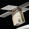
Lunar Flashlight (LF) was a 6-U CubeSat originally developed at JPL that was designed to detect water ice on the south pole of the moon. GT was selected to design the propulsion system in conjunction with MSFC. After GT's initial involvement designing the propulsion system, GT was selected to integrate the spacecraft and perform mission operations.
I got involved with the integration and test campaign while I was finishing my undergrad degree. After being hired full-time at GTRI, I continued my work on LF, delivering the CubeSat for launch in late 2022 and performing mission operations through summer 2023. LF ultimately failed to reach the moon, but working on this project was incredibly rewarding and a highlight of my career. This page covers my involvement with LF from it first arriving at GT in Summer 2021 to us saying goodbye in December 2023.
Background
So why go to the moon and look for water ice at the south pole? And how do we know there’s water there in the first place?
Because of the geometry of certain craters on the south pole of the moon, there are areas on the south pole that have not seen sunlight in millions of years. These regions have extremely low temperatures and any water that found its way to these locations could be trapped and form deposits. There have been several missions that were designed to detect water on the moon. One of my favorite examples is the LCROSS mission, which smashed the upper stage of a rocket into a crater to expel a dust cloud which a second spacecraft would then fly through to measure the water content of the ejected regolith.
So while we know there is water ice on the south pole of the moon, it is still an open question of where the water ice is precisely located. Enter Lunar Flashlight. By carrying high power infrared lasers and a detector capable of measuring the reflected laser signal from the lunar surface, Lunar Flashlight could determine the distribution of the water ice in 2-D at a higher resolution than any previous mission. We had a wonderful science team for this mission and you can find a fantastic article on the instrument and the designed science mission here (Cohen et al., 2024).
Integration
Putting all the pieces together
We had a propulsion system that was fabricated at GT and an avionics assembly that was assembled at JPL. While both systems had undergone some system-level testing, they had never been tested as a unit. When the upper avionics assembly arrived at GT, it would be the first time ever that the flight systems would be connected. We had to take this from a collection of separate parts, to a fully-assembled CubeSat ready for launch in just a few months.

I was thrown into this project in June 2021, about two months before the bus was scheduled to arrive. I was responsible for writing procedures on how to assemble a CubeSat that I hadn’t even seen in person yet. I spent almost every day meeting with JPL engineers and students within SSDL at GT to figure out how we were going to put this thing together. It was stressful but extremely rewarding at the same time.
The bus arrived at GT in August 2021. Our original schedule was tight as we originally thought we would be delivering LF for launch on the Artemis 1 mission. The project quickly decided though that it would be better to skip the Artemis 1 launch and give us more time to fully assembly and test LF.

Our first task was to get the propulsion system connected mechanically and electrically to the upper avionics assembly. Mechanical integration didn’t present much of a risk to the hardware. If we found a problem, we could just pause and things would stay safe where they were. Initial fit checks went smoothly and it only took us a couple days to complete the propulsion system mechanical integration.
Electrical integration, on the other hand, was a much riskier operation. GT and JPL had worked together to define the propulsion system interface, agreeing on what pins should be where, what voltage levels should be provided, what connector to use, etc. But mistakes happen. Pins can get swapped inadvertently. A cabling harness might be designed to an older specification. Design changes might never get communicated to the other team. If you ever fry a component in the lab, you just grab a new part, replace the dead one, and move on with testing. But there was no new part for the propulsion system — this was a one-of-a-kind system that had taken years to build. Messing up the propulsion system was not an option. We couldn’t make any mistakes.
This is where I learned a very important lesson about how engineers working with space hardware approach these massive projects and it’s stuck with me to this day: Mistakes are inevitable, but we can design a process that is resilient to these mistakes.
JPL doesn’t expect engineers to be perfect machines, in fact, they assume the opposite — that every engineer is human and mistakes are inevitable. By acknowledging this so openly and plainly, we can make plans on how to minimize the impacts of any mistakes.
One saying I’ve heard a lot in my work with JPL is “Trust, but verify.” We knew that JPL had designed the propulsion system to the specifications given by GT, but what if an innocent mistake had happened along the way? So for our propulsion system electrical testing, we would perform a “safe-to-mate” before connecting the two systems together. A safe-to-mate is a manual check of every wire in a connector to verify that voltage levels are safe and the pin-out matches the design.
To do this, we had to design an adapter that would take the propulsion system cables and break it out to a easily probed interface. This was my first time outside of coursework designing a PCB and I was happy to make a PCB that would actually serve a real purpose. I sat down at my computer one afternoon, launched Eagle, and came up with the board in the picture below:

Looking back at it now, it’s as basic of a PCB as you can get. I don’t know if I would even mention this PCB in an interview if asked about all of my design experience. But it was still my first actual PCB and it holds a special place in my engineering heart (questionable routing and design choices aside).
We were able to complete the majority of the integration campaign in about 4-5 months. But now that we had a fully assembled CubeSat, we still had a long way to go to getting it into space.
Test
Making sure this thing works
It’s already difficult enough to design and assemble a CubeSat capable of surviving the space environment. But it’s an entirely different undertaking to prove that what we built would perform exactly as it was designed. For every system on LF, we had to design tests that would show that every part performed exactly within its specification.
Some tests were simple, such as showing that power would turn on when we were deployed from the launch vehicle. But many of the tests were quite involved and required weeks and months of planning for a test that could take weeks to run. One of the major tests any spacecraft undergoes is a thermal vacuum (TVAC) test. During TVAC, you put your spacecraft in a chamber that can go to extremely low pressures while exposing the hardware to temperatures ranging from -20 to +50 °C. Whenever the hardware is in the TVAC chamber, it has to be monitored 24/7. So while this test was going on for 10 days, I took turns with my peers staying up late into the night to monitor the hardware and make sure nothing went wrong. While the hardware came out unscathed, the same couldn’t be said for my sleep schedule.

After several months and many, many, long nights, we completed all of the major testing milestones that we had set. LF was ready for launch. We shipped LF off to Marshall Space Flight Center for fueling and then brought it down to Kennedy Space center for launch vehicle integration. It was only a few weeks until we would be operating an interplanetary CubeSat.
Launch
Getting LF off the ground
Whenever we first delivered LF to SpaceX for launch, we thought that we would launch in just a couple weeks. But things always end up getting pushed back and our launch date slipped several times. Sometimes the decision to scrub a launch would come only hours before we were supposed to launch, so we would already be in our mission operations center at GT, getting ready when we were told to stop and head home for the night.
But eventually, we got off the ground. Lunar Flashlight officially launched on Sunday, December 11 at 2:38 a.m ET. Here’s the video of our launch with official deployment of LF happening 1:11:00 in the video.
Once we deployed, our radio wouldn’t turn on immediately. So after deployment, we spent the next several minutes waiting to get a report from Deep Space Network that they saw our signal. You can see the moment we first ever talked to Lunar Flashlight in space here:
Operations
Wishing that LF was on the ground
End of Mission
Saying goodbye
Eventually, it became clear that we weren’t going to make it to the moon. It had taken many months, and the team had given absolutely everything we had to troubleshooting LF, but this was a problem that just couldn’t be solved in space. The project made the official decision to call off recovery efforts on the propulsion system. As LF swung by Earth for one final pass, it gained enough energy to be ejected from the Earth-Moon system. While we passed by Earth, we captured this image with our star tracker:

But even with the main mission over, we didn’t let the opportunity go to waste. It’s not often that you get to work with an interplanetary CubeSat and the team at GT made the best of it.
References
2024
-
 Lunar Flashlight science ground and flight measurements and operations using a multi-band laser reflectometerIcarus, 2024
