Ground Station Install in Fairbanks, Alaska
There’s an upcoming mission in the Space System Design Lab at Georgia Tech called VISORS, which stands for Virtual Super-Resolution Optics Using Reconfigurable Swarms. VISORS consists of two cubesats that fly in close proximity to eachother to image the sun’s corona. Operations will happen out of Georgia Tech using our ground stations.
I work on our ground stations at Tech, but in the past couple of years, we haven’t had to support many missions. Lunar Flashlight was our last big mission, and that used the Deep Space Network to provide communication. VISORS is one of the first missions we’ve had in a while that will rely heavily on our ground stations.
However, VISORS is launching into a near polar orbit. This means that in Atlanta, GA, we would only get two ~15 minute passes each day at best – not nearly enough to support the data downlink we need for the mission. So we’re collaborating with several universities to increase our ground station coverage. The Laboratory for Atmospheric and Space Physics (LASP) and the University of Alaska Fairbanks allowed us to stick an antenna on their existing masthead up at the Poker Flats test range. Due to its geographic location, this ground station should have the VISORS satellites in its view multiple times a day. I went up in early June to get our ground station equipment set up and wanted to write a bit about the process in this post.
Hardware
We have several different ground stations at Georgia Tech and they all have slightly different hardware which makes maintaining them cumbersome. For VISORS, I wanted to develop a set of hardware that would be easily deployable to other locations and give good performance. VISORS also gave me a good excuse to do this anyway, as it’s using the 401 MHz band versus the amateur band that many satellites use for their UHF communications. Supporting the 401 MHz band meant revamping a lot of the equipment at our ground stations.
Here’s a breakdown of the major components that make up our stations:
- Ettus B210 Radio
- Empower RF 1094 20 - 520 MHz 100 Watt Amplifier
- M2 Antenna Systems 402CP43 Yagi Antenna
- Yaesu Rotator
- Mini-circuits ZKL-33-ULNS+ Low Noise Amplifier
- Custom RF Relay Board
- Custom TX/RX sequencer Board
Our system is half-duplex so I had to find a way to sequence the TX/RX switching. I did this using a custom board that would take in inputs from the B210 and control the biasing of some custom relay boards. This board also controls the amplifier power, monitors input power levels to protect the amplifier, and provides some basic health telemetry over the arduino’s serial port.
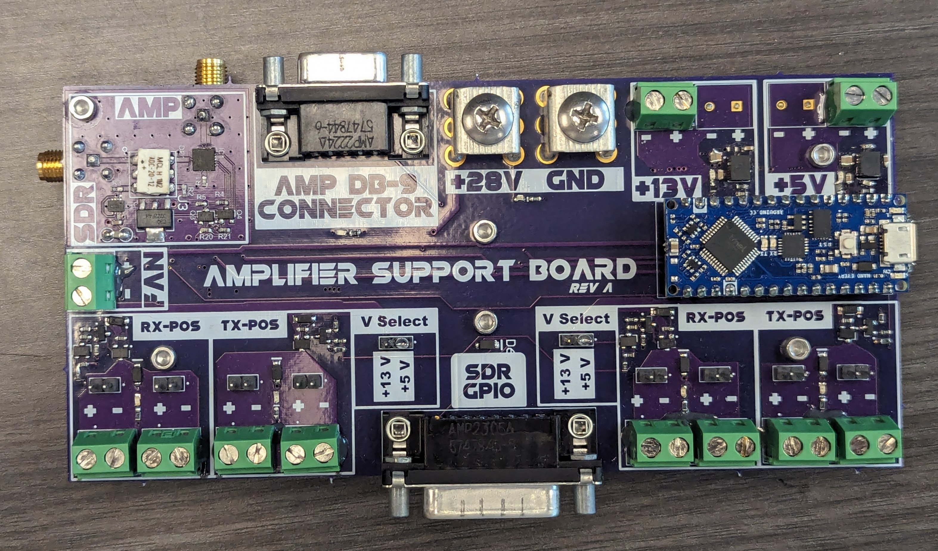
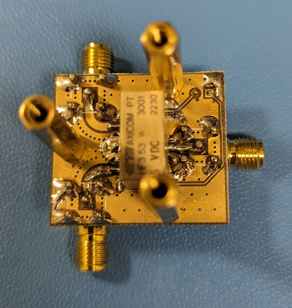
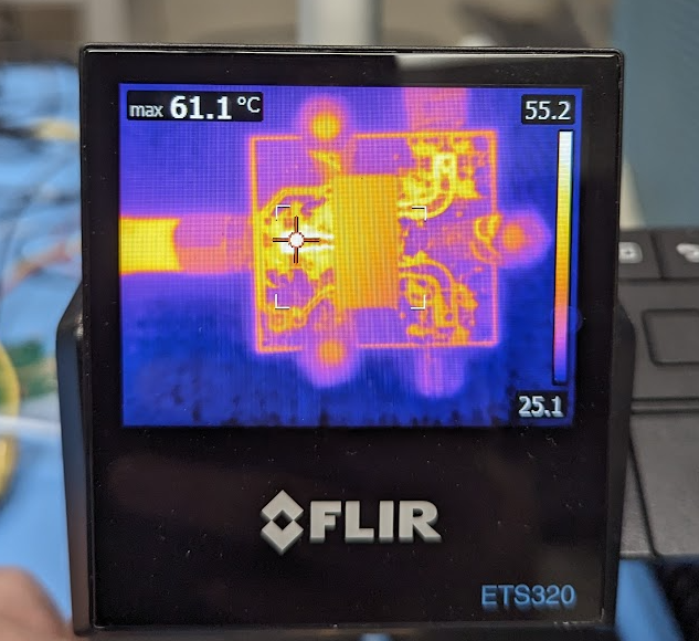
Top: Relay Board PCB
Bottom: IR View of Relay Stress Test
HF3 Relays
RF relays can be expensive, especially for higher power options. There’s some good test data here by an amateur radio operator, where they measured the performance of cheaper relay options. I ended up designing a board around the HF3 relay. This relay series is listed as handling a maximum 50 watts, but I was able to test these relay boards up to 120 watts of power at 400 MHz. They got warm, but nothing outside of their operating range given in the datasheet. I’m assuming that the 50 watt number given in the data sheet is the maximum of amount of power the relay can dissipate internally at the worst case insertion loss of roughly 0.35 dB at 2.5 Ghz. In this case, 50 watts in yields ~4 watts of internal power dissipation. The insertion loss at 400 MHz is much lower, only 0.12 dB. If you set a maximum internal dissipation limit of 4 watts, the relay could theoretically handle up to ~150 watts of power at 400 MHz. I didn’t test up to this, but there’s a chance it could handle it.
The IR image on the right is the result of letting the RF relay sit for an hour with 120 watts of power passing through it at 400 MHz. It was hot to the touch, but still within the limits set in the datasheet. I wanted to really stress test these relays, so I set them up for a day of hot switching at 10 Hz with 120 watts of RF power. Testing them afterwards showed that they still met the specifications given in the datasheet. I’m sure that running these at 120 watts will reduce their lifetime, but given how (relatively) cheap these things are, that’s not a huge problem. Total cost for the boards, connectors, and parts came out to around $30 per relay, which is pretty cheap to some of the commercially available options.
Putting it all together
I ran out of time to design a rack mountable enclosure for all of the elements that needed to sit inside the shack near the computer. This hardware was going to be thousands of miles away from Georgia Tech and I wanted to make sure a loose wire or part wouldn’t take the system down. With not enough time left to mount everything, I ended up going with the next best option: glueing everything together. I needed the system to be compact so I just mounted as many components to the amplifier + heatsink assembly as I could. We had some expired 2216 epoxy lying around lab that I used – it wasn’t acceptable for use on cubesats anymore but it could hold some relay boards to the amplifiers just fine. I ended up creating this wonderful assembly:
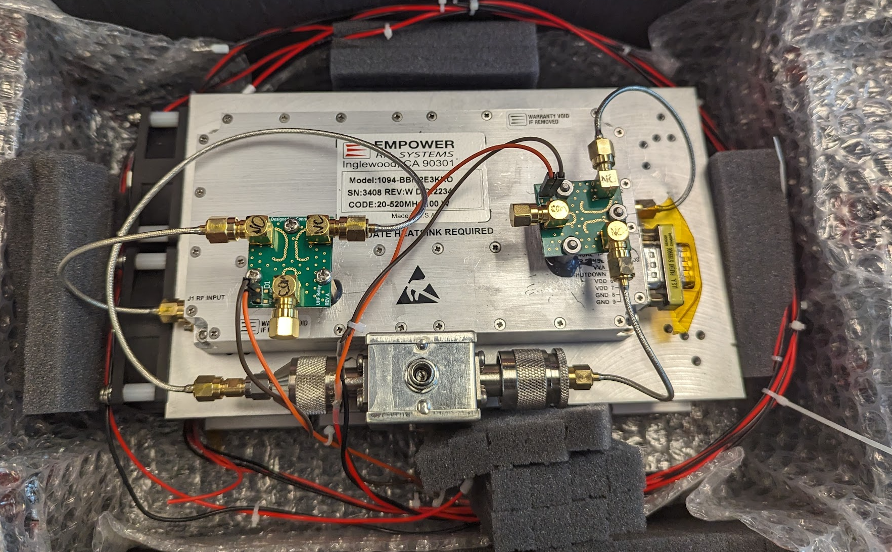
The big aluminum block in the center of the image is the RF amplifier. Below that is its heatsink. I have two of my relay boards attached to the top for TX/RX path switching. At the bottom of the amplifier is the bias-tee which provides power on the RX path for the low-noise amplifier that sits right next to the antenna. All of the SMA cables are hand formable semi-rigid cables which provide very low insertion losses with high power handling. This assembly is controlled by the amplifier switch board and the relays connect directly to the antenna feed line and the SDR.
In Alaska
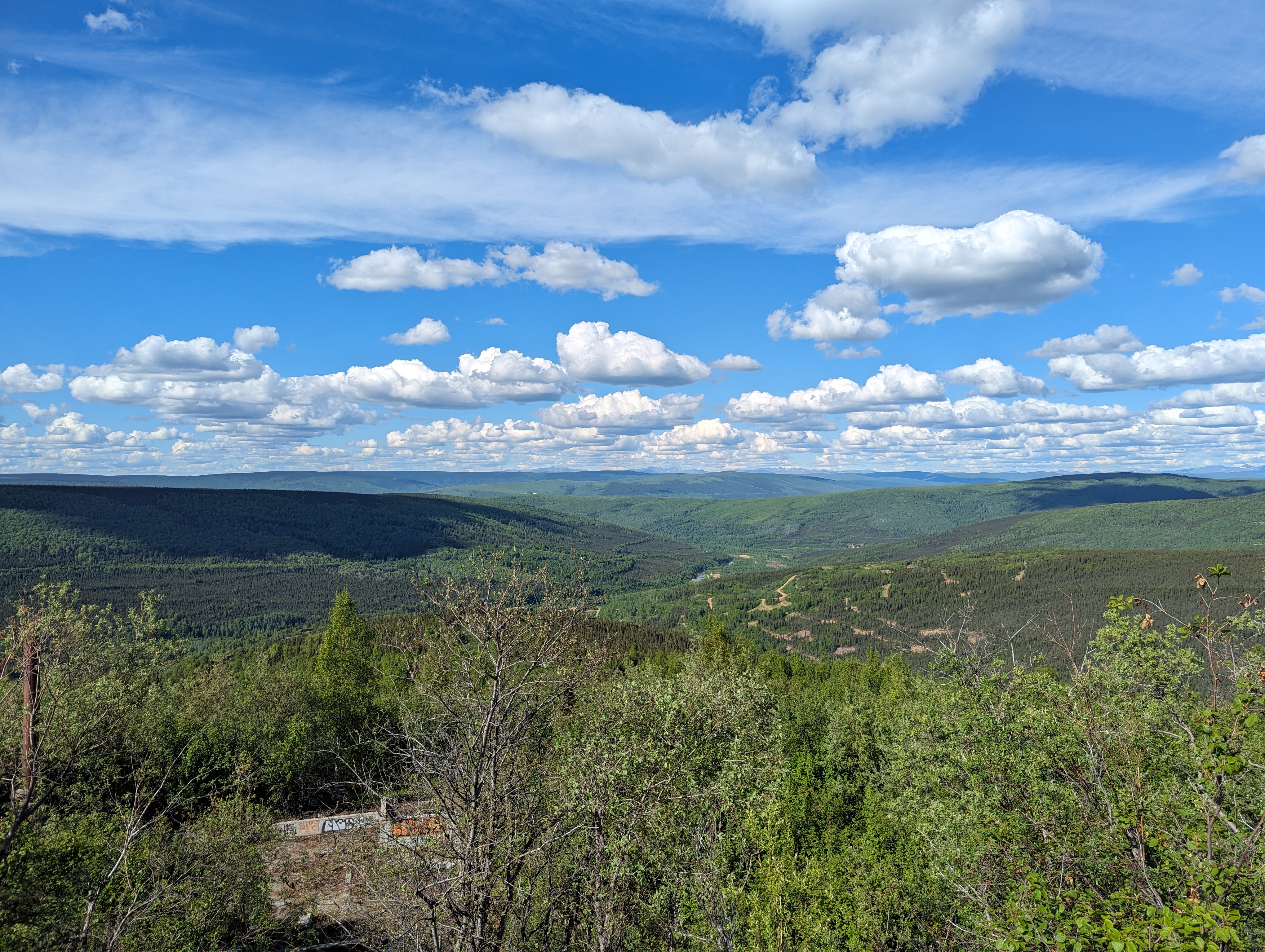
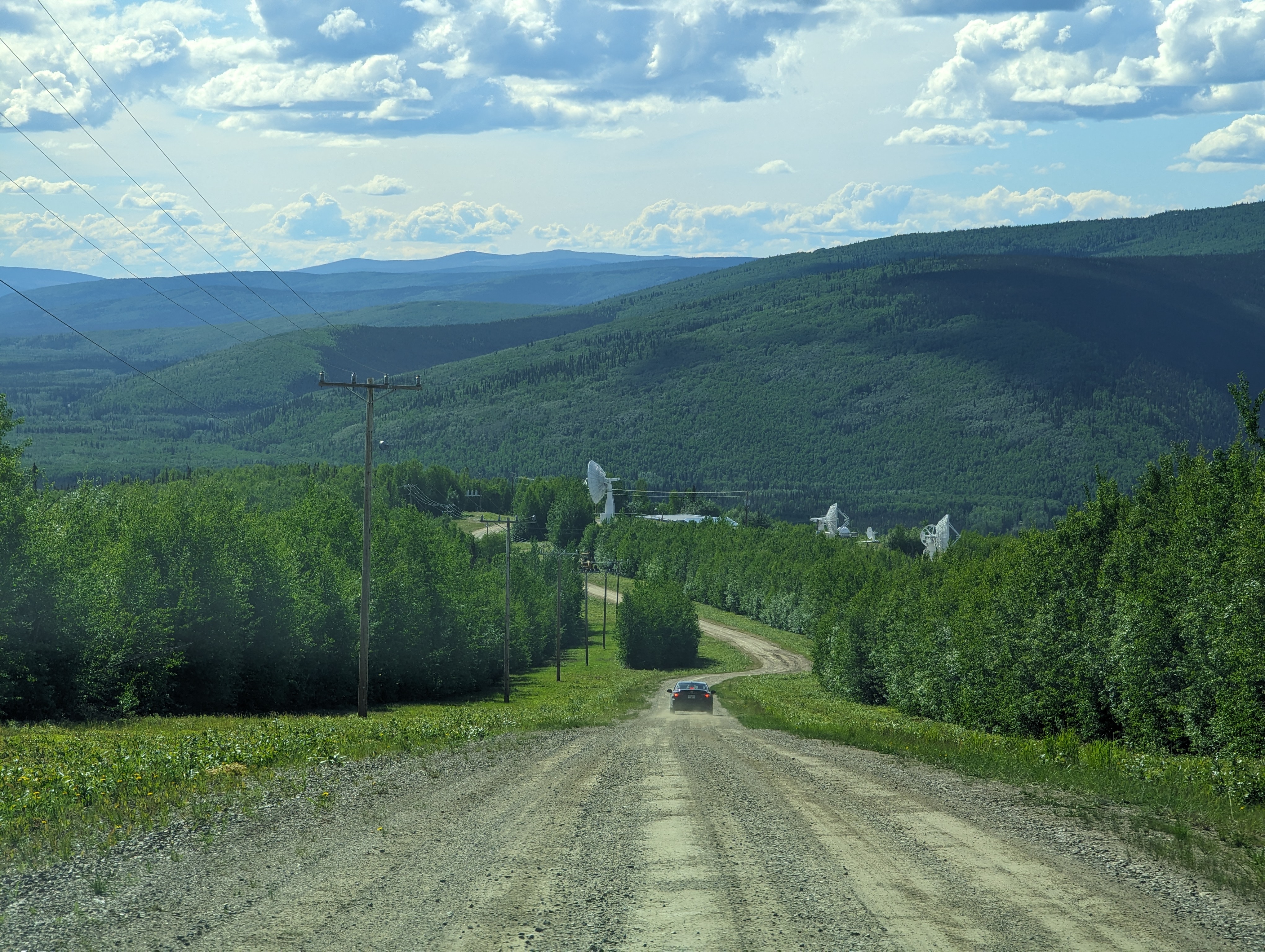
The ground station was set up on top of a hill at the Poker Flat Research Range – a research facility that launches sounding rockets for a variety of scientific purposes. During the winters, when the sun never rises, there’s a facility on the same hill as the ground station that serves as a home base for visiting researchers studying the aurora. Sadly, I visited during the summer when the sun never sets so there was no chance of seeing the northern lights.
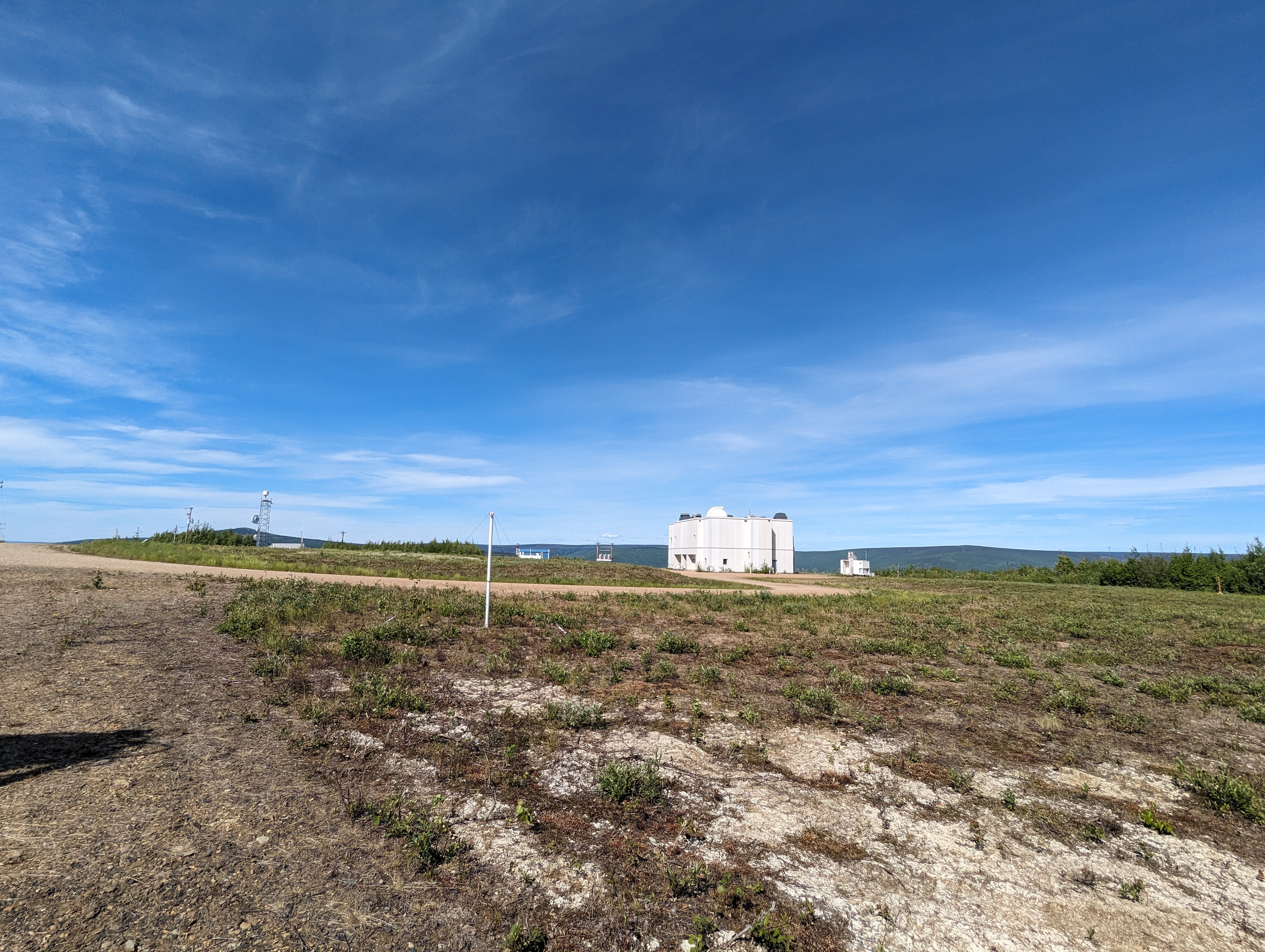
You can see why this hill makes a good location for a ground station – there’s excellent horizon-to-horizon coverage with minimal obstructions. Whenever I arrived at Poker Flat, I worked with two engineers from LASP to get all the ground station equipment installed (LASP is technically responsible for maintaining the site; they were just nice enough to offer us a spot on their mast head up here to use for the duration of VISORS). LASP had already completed much of the hard work when I arrived, making my job a lot easier.
The first day was mainly getting some network configuration figured out so we could talk to the computer from GT remotely. I also took the opportunity to get the low-noise amplifier mounted to the masthead as close as possible to the antenna. This helps preserve as much of the signal as possible before its sent across the long feed lines to the radio.
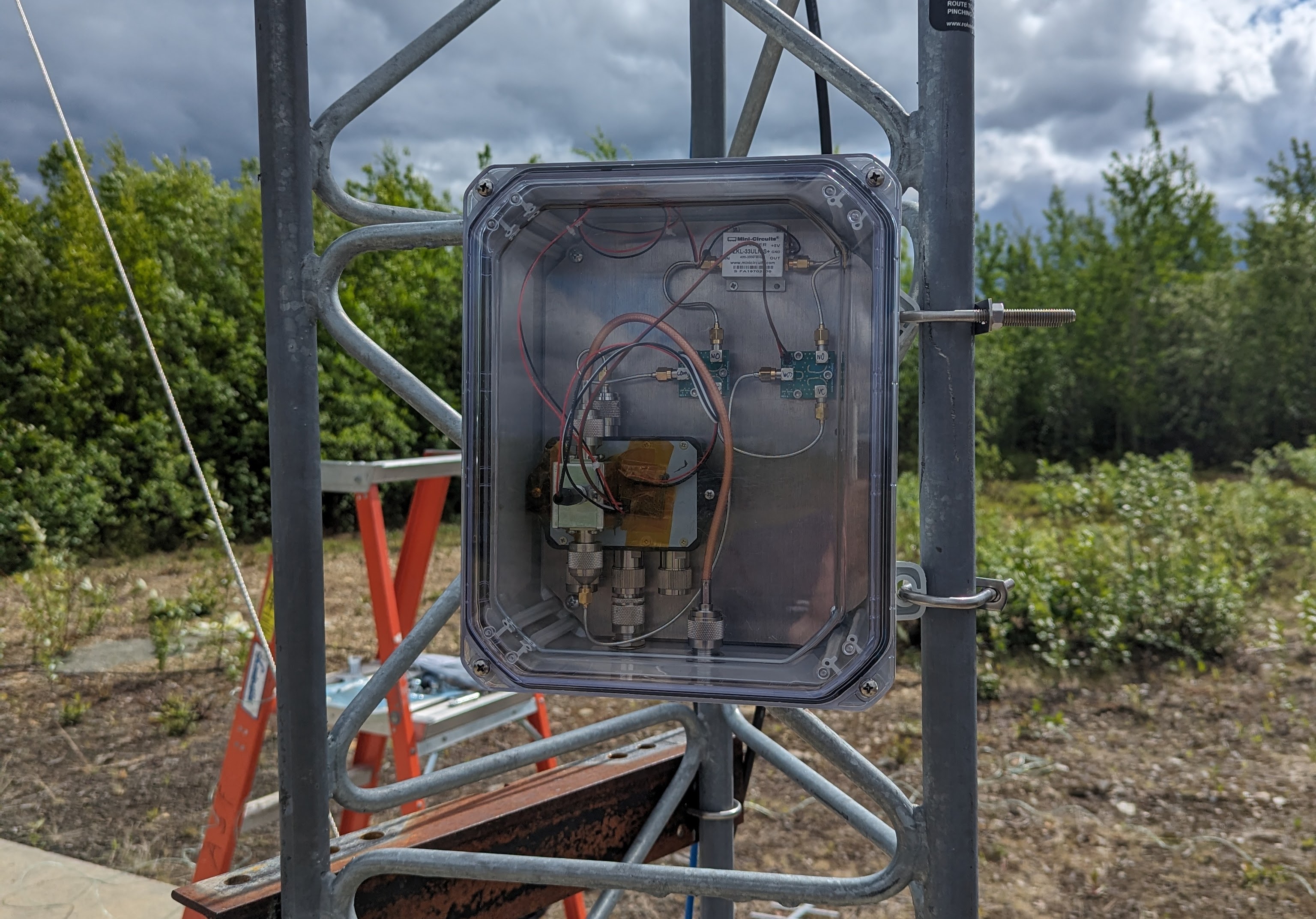
The second day, we focused on getting the entire system integrated end-to-end. This involved setting up the high power amplifier assembly, sequencer controller, radio, and rotator control software. Everything went smoothly, and by the end of it, we had a completed system. All that was left was to test it.
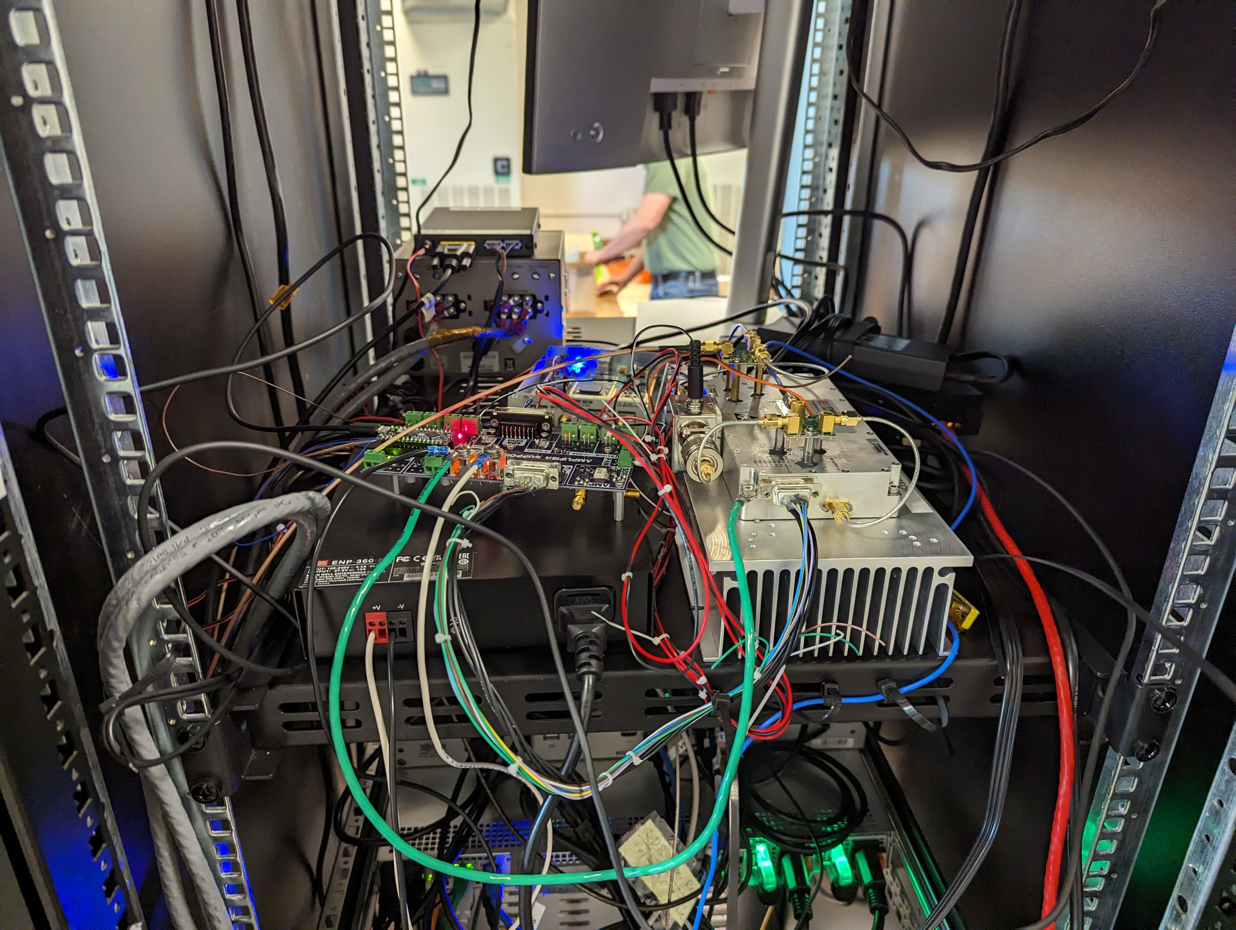
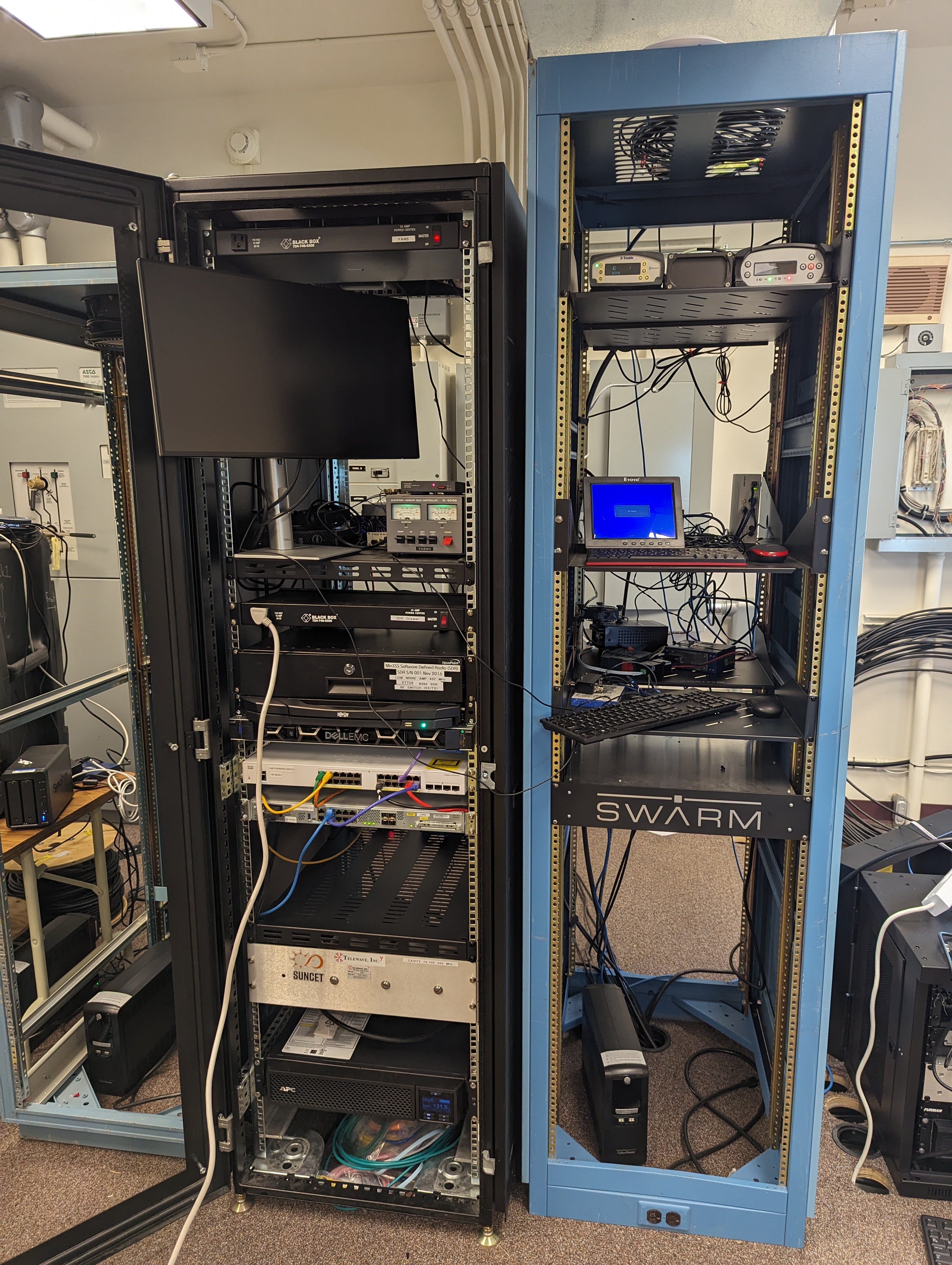
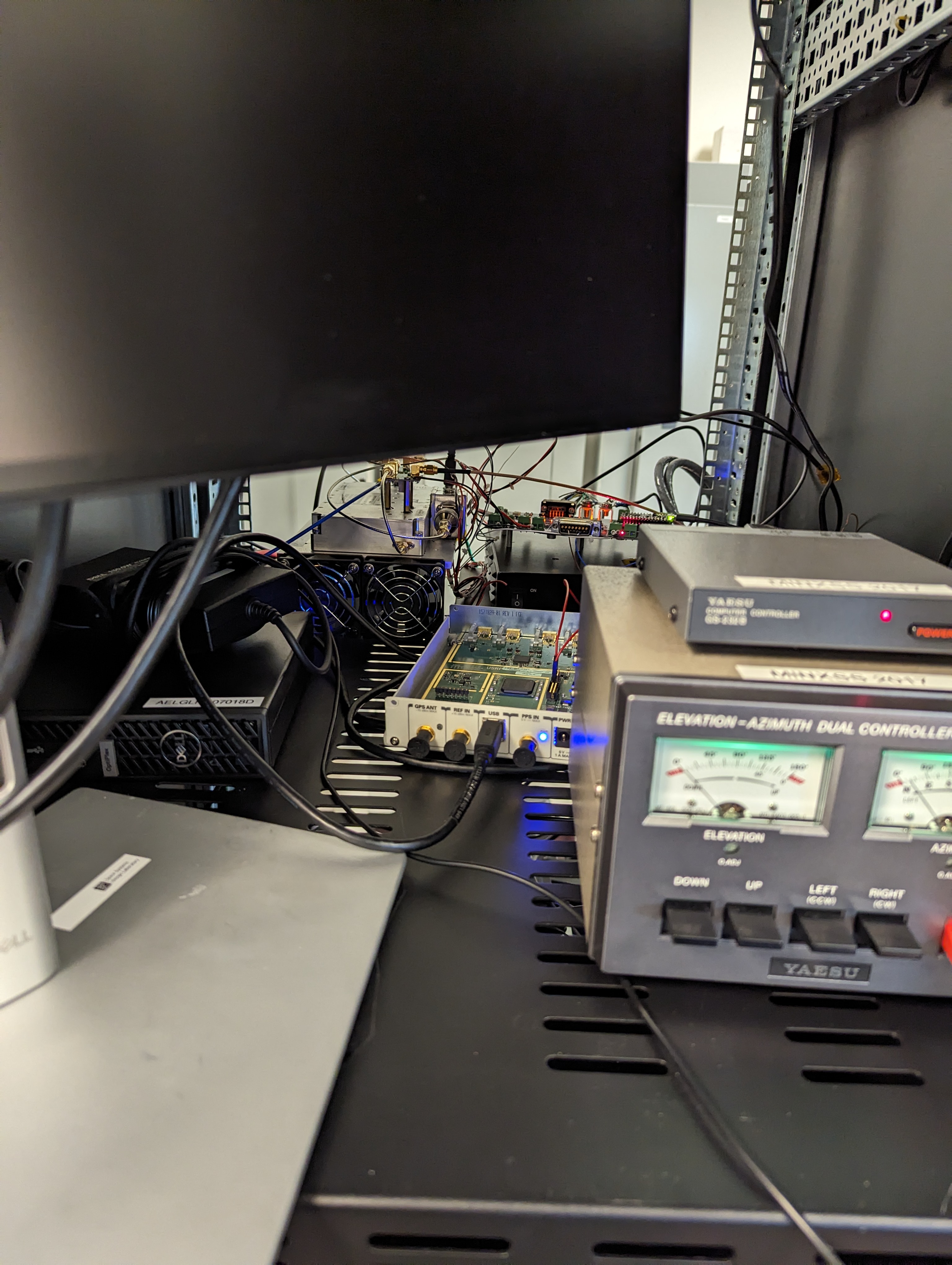
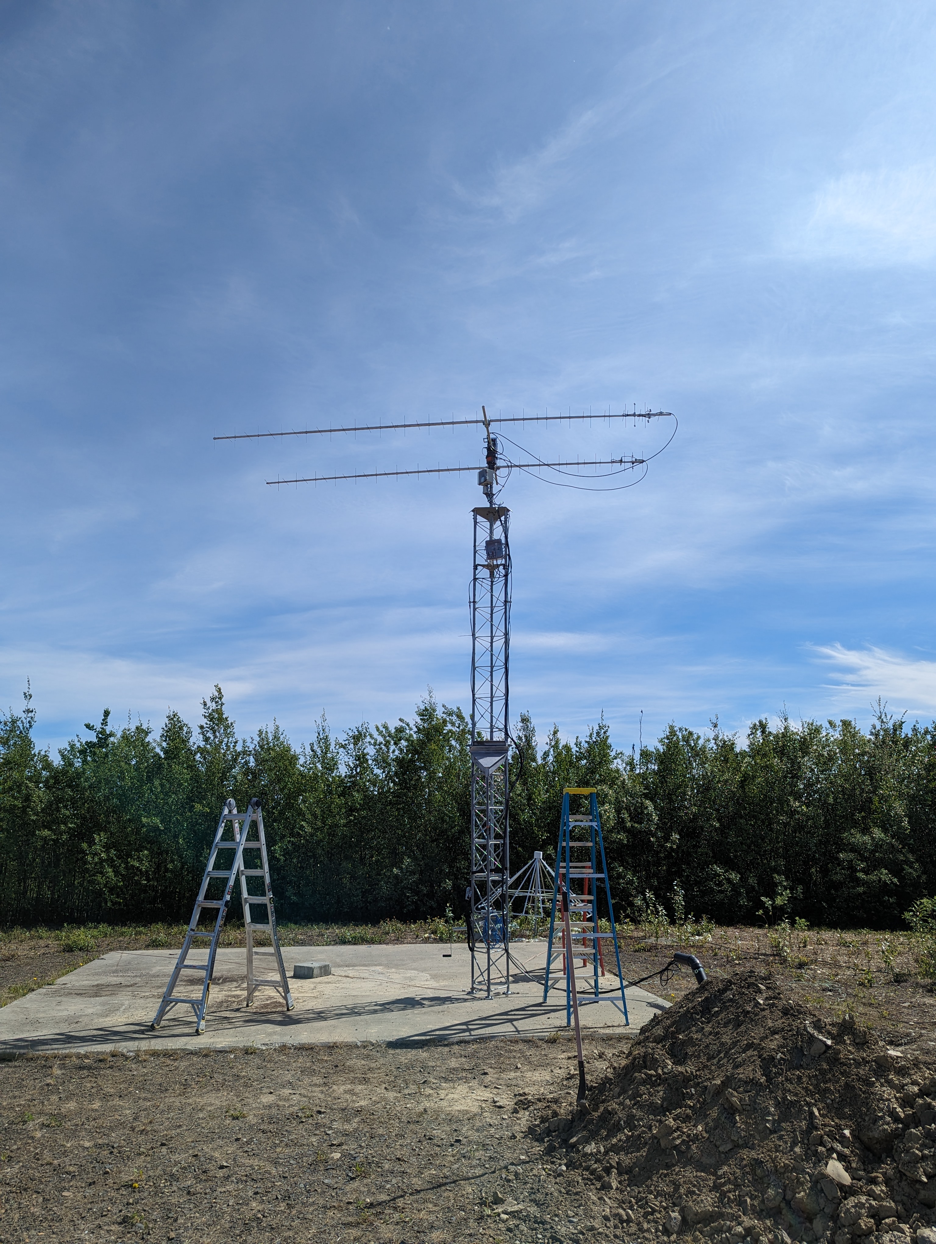
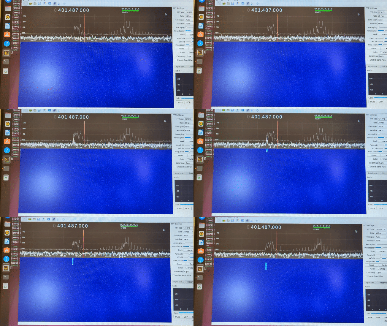
I had tested the transmitter down at GT, but we wanted to do a simple verification on-site to verify nothing had broken in transit. We set up a separate small Yagi and verified that the output power received from the transmitting antenna seemed roughly correct. Everything looked nominal. To test the receive, we used the Satnogs database to find active satellites that were transmitting in the 400 MHz range. Due to our location, we were able to consistently find satellites overhead that we could use to test. After a couple of passes where we didn’t hear anything, there was a pass with an amateur russian satellite that had a strong beacon. You can see in the gif below one of the beacons towards the end of the pass. I had peak hold turned on so you can see in the peak history how the frequency of the satellite shifted over the course of the pass.
The next day was mainly just cleanup and organization of the ground station hardware, there wasn’t much left to do. The ground station was completely set up and ready to support the VISORS mission whenever it launches.
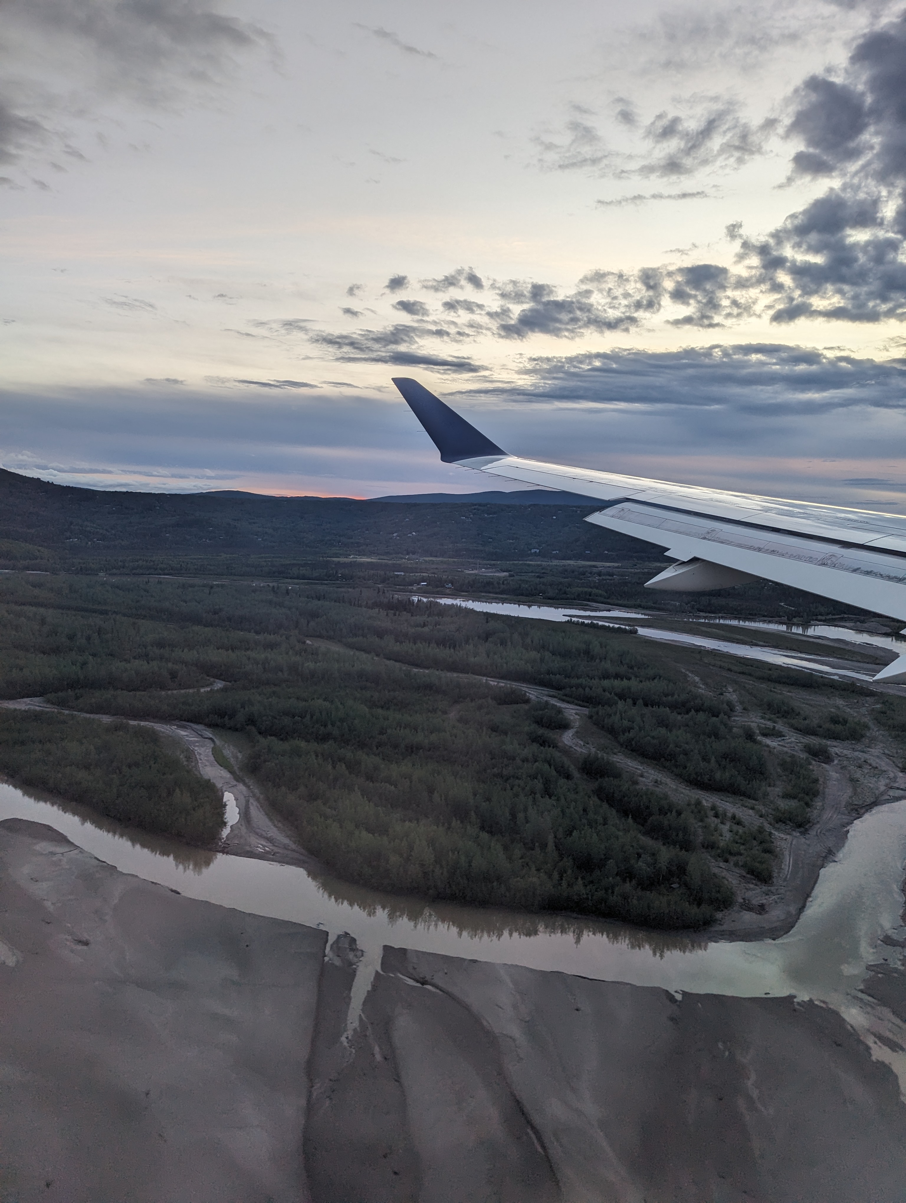
Small note: being in Alaska was a fun trip, but getting there was one of the worst travel experiences I’ve ever had due to delayed flights, cancelled flights, and overbookings. I wanted to try and explore some of the national parks around Fairbanks but was unable because I arrived to Fairbanks later than I expected. I’ll try and get back to Alaska at some point to see Denali and the other parks. In the meantime, here’s some pictures of the views around Fairbanks and Poker Flat:

